
Background
Fiber optic networks have grown immensely at a very rapid pace throughout history. As the need to send data at higher capacities over longer distances grew over time, fiber optic professionals developed specific wavelength windows that allowed for longer transmission. As discussed in our previous blog on optical return loss, “FAQ: Why don’t you sell 70km CWDM 10G optics in the 1350-1450 range?”, these wavelength windows were confined to the 1310nm and 1550nm regions to prevent high degrees of attenuation and return loss. Although this appeared to be the simple solution to successful data transmission, limitations due to dispersion began to occur as networks advanced.
The first optical fibers used throughout networks were known as multimode step-index fiber. This type of fiber experienced several varieties of dispersion. Multimode graded-index fiber was engineered soon thereafter, but it also experienced similar issues with dispersion. A breakthrough in fiber optic technology occurred when single-mode fiber was introduced in 1970; it eliminated a majority of the dispersion issues attributed to multi-mode fiber. Single-mode fiber still experiences some types of dispersion over long haul networks, but is the most reliable solution introduced thus far. This explains why most current long haul high-speed fiber optic networks rely primarily on single mode fiber.
Why is Dispersion Important?
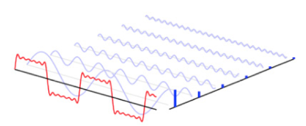
Throughout the physical layer of fiber optic networks, as with all forms of signal propagation, the modulated information signal is generated as an infinite sum of orthogonal basis functions. The proper linear combination of these basis functions generates the optical signal that travels down the fiber. The basic concept that underlies this process is known as Fourier Analysis. Fourier Analysis is the spectral study of the decomposition and recomposition of a signal in to its orthogonal complex frequency components (sines and cosines). In other words, any continuous function can be produced as an infinite sum of weighted sines and cosines. Because we can decompose the modulated optical signal into frequency components that span a finite bandwidth and that the fibers index of refraction is a function of optical wavelength (or frequency) we can expect that the various components of the composite waveform will travel at different velocities through the fiber. The result is a localized time spreading of the signal as it travels down the fiber known as dispersion. This spreading of the signal adversely affects the information carrying capacity of the fiber or restricts the fiber length.

For the purposes of this blog, we will focus on the various modes of dispersion throughout single-mode fiber, its impacts to the information signal, and the associated testing procedures.
Dispersion and Its Types
There are several specific types of dispersion that affect single-mode fiber, including:
- Polarization Mode Dispersion
- Material Dispersion
- Waveguide Dispersion
- Chromatic Dispersion
Single-Mode Fiber Dispersion
The introduction of single-mode fiber solved a majority of multimode attributed dispersion errors, but did not eliminate dispersion errors altogether. What remains are chromatic dispersion and polarization mode dispersion.
Chromatic Dispersion occurs when single-mode glass fibers transmit light that contain different wavelengths traveling at different speeds. The different wavelengths (colors) traveling at different speeds create a pulse that spreads, and this leads to distortion in the data transmission.
What Causes Chromatic Dispersion?
There are two main factors that cause chromatic dispersion: material dispersion and waveguide dispersion.
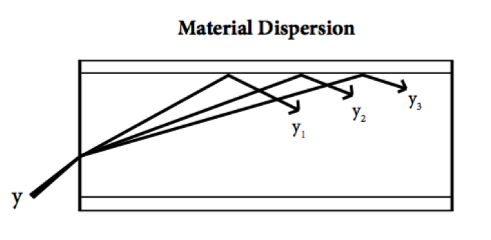
Material dispersion is a dependence of the fibers refractive index on the transmitted signals wavelength or frequency. This type of dispersion results from the interaction of the signal with the crystalline structure of the fiber optic glass. The refractive index of the glass material varies according to the wavelength of the optical signal; the longer the wavelength, the faster the signal travels. The various wavelengths traveling at different velocities create a variation of optical pulses that spread. This, as a result, causes some pulses to spread in time. As wavelength increases and frequency decreases, material dispersion decreases. As a result, optical signals in the 1550 nm range generally experience less material dispersion than optical signals in the 1310 nm range.
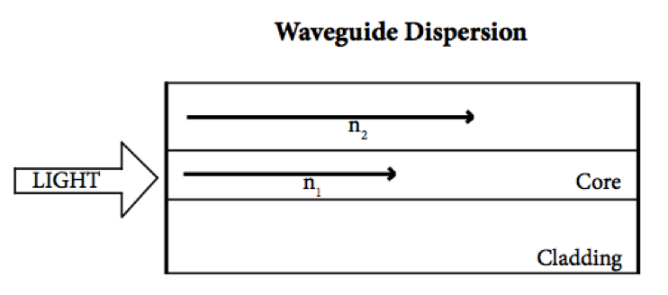
Waveguide dispersion is caused by differing refractive indexes between the core and cladding of an optical fiber. Due to the nature of fiber optic transport, a small amount of light travels to the cladding from the core, causing signals to travel at different speeds.
Polarization Mode Dispersion
Polarization Mode Dispersion (PMD) is prevalent in single mode fiber. A standard light pulse is composed of two polarization modes, which travel perpendicular to each other. In a “perfect” optical fiber, these polarization modes would travel at the same speed and no PMD would occur; however, there is usually a certain degree of imperfection throughout the fiber that causes the two modes to travel at different speeds. Some fiber imperfections that cause PMD include core stress, cladding eccentricity, fiber twist, fiber stress, fiber bend, etc.
Testing Procedures
There are several ways to test for Chromatic Dispersion; all methods involve testing at a range of wavelengths using distinct sources of wavelengths, a tunable laser, or broadband source with a monochromator. Testing generally requires access to both ends of the fiber and a second fiber will be needed to synchronize the two testing instruments at both ends. Chromatic Dispersion testing is usually performed during or shortly after a fiber installation, after any type of fiber maintenance, or before an upgrade to higher bit rates.
As for Polarization Mode Dispersion, it is important to test when the transmission bit rate per channel increases or distance increases. PMD is usually tested on recently installed fibers that will have use throughout long haul, high speed networks over 2.5Gb/s. There are several ways to test; all methods have a source that can vary the polarization of the test signal and also a measurement unit that can analyze changes in the polarization. Several of these methods include wavelength scanning and Stokes Parameter Evaluation, interferometry (traditional and generalized methods). Testing accuracy is generally difficult; the degree of uncertainty ranges from 10% to 20%.
For more information on dispersion or optical transceivers, contact us at marketing@precisionot.com