
Get to Know Your MPO
MPO (Multifiber Push On) connectors were the first connectors designed to house multiple optical fibers in a single ferrule. Multifiber cables with MPOs support the many high density/high bandwidth applications desired by today’s telecom market. MPOs help promote well-organized cabling and are great for future-proofing data centers and other optical networks due to their flexibility, reliability, and scalability. MPO cables commonly pack 8 to 24 fibers into a single cable making it possible to expand capacity and migrate from a 10G to a 40G or even 100G and 400G network. However, ensuring the proper polarity of these connections using multi-fiber MPOs from end-to-end can be challenging. We’ll provide some basic info here to help reduce frustration when working with MPO connectors and cables.
Connectors
Note that MTP® is a registered trademark of an MPO manufactured by US Conec. All MTPs® are MPOs, but not all MPOs are MTPs® as the latter is designed with some enhanced features. For our purposes MPO/MTP® can be used interchangeably and throughout the document we’ll refer to the generic version, MPO.
The most common strand counts for multi-fiber cables utilizing MPOs are 8, 12, 16, and 24 strand. As shown in the examples in Figures 1 and 2, MPO connectors have several visible features which help identify how the cable will function. These features include the key, fiber strands, alignment pins/sockets and a white dot on the side that serves as a visual cue to indicate where position 1 is.
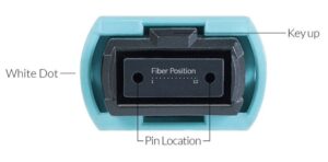
Fig. 1 12 Fiber MPO Connector Endface
The white dot will always be on the side of Fiber Position 1. Fiber POSITION will NEVER change: that is, Position 1 will always refer to the position shown on the side with the white dot. What changes is the arrangement of the fibers going into each position.
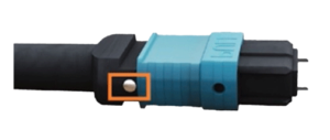
The alignment pins help indicate whether an MPO cable is Male or Female. Pins identify that it’s a Male connector; no pins indicates a female connector. Every connection requires a male to female.
Fig. 2 Side View of MPO Connector
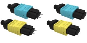
Fig. 3 Male (with pins) and Female (no pins) connectors
12 fiber and 24 fiber type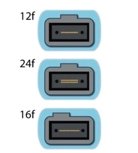 connectors can plug into the same adapter/mating-sleeve/port, however 12 fiber will not line up with either row of the 24 fiber. Because 24 fiber has two rows with 12 positions in each, when mated using a typical Type A adapter(see Fig. 10 in the section below on adapters), Position 1 will mate up to Position 13. Knowing your fiber count and polarity are essential to making a reliable connection.
16 fiber has a shifted key and the pins/pin-holes are closer to the edges. This means that a 16 fiber cannot mate to a 12 or 24 fiber. The shifted key also prevents damage from the pins to the end face by attempting to mate the wrong fiber counts together.
Connector End Faces
Ultra Physical Contact (UPC) connectors and Angled Physical Contact (APC) 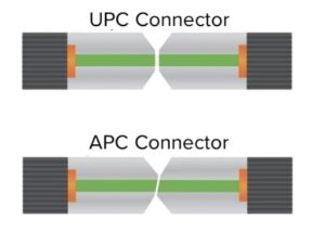 are both commonplace in modern fiber optic network designs, but they each work best in specific use cases. The connectors are often referred to in terms of their polish types as described below:
UPC = ultra polish connector → polished at 0 degree
APC = angled polish connector → polished at 10 degree angle
In general, Multimode fiber uses a 0 degree polished end face (UPC) while Single mode fiber uses an angled end face (APC). This is why angled connectors must use Type A adapters (Key-Up to Key-Down) when mated together as shown in Fig. 6.
Top, Fig. 4 12, 16 and 24 Fiber MPO Connectors
Bottom, Fig. 5 UPC and APC Polish Types
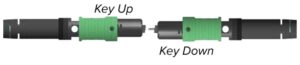
Fig. 6 Angled (APC) Connectors in Key Up / Key Down Configuration
Polarity
Polarity refers to the positioning of the fiber strands inside the cable and the direction that the signal travels along the fibers. It’s sometimes also referred to as “mapping” or “routing”. In order for a system to work, it’s critical to have proper connections wherever transmitters are connected to receivers. For a standard Duplex LC Fiber which has 1 transmit lane and 1 receive lane this is rather simple. But things get quite a bit more complicated with MPO cables due to the fact that each cable contains multiple fibers and different applications/use cases require different configurations. This is why there are 3 types of polarity when it comes to MPO cables.
Type A is shown at the top of Fig. 7. With these cables position 1 in the first connector maps to position 1 in the other connector. The same is true for all subsequent fiber strands, so position 12 in one connector maps to position 12 in another connector and so on. Notice the Key-Up to Key-Down positioning to make this possible.

Fig. 7 Type A “Straight Through” and Type B “Cross Over” Polarity
In Type B shown at the bottom of Fig. 7 (also known as “Rollover”, “Cross Over”, or “Reversed”), position 1 in one connector ends up in position 12 in the other connector. Type B cables are quite popular and very useful for making direct connections between 40G QSFP / QSFP+ Transceivers with MPO connectors which utilize 4x 10G transmitter lanes and 4x 10G receive lanes to achieve 40G connections.
Type C cable polarity is similar to Type A, except that in Type C each pair of fibers is criss-crossed such that a fiber in position 1 on one connector will arrive in position 2 on another connector. This polarity type is less common but may be helpful for certain use cases.
With MPO cables there’s two main types of applications: a point to point MPO to MPO and a breakout MPO to LC/SC connectors. For point to point applications the polarity type will depend on the use case for the customer.
For a breakout options and as an example shown in Figure 9 below, the polarity is controlled by the position and pairing of the LC connectors.
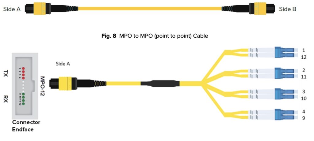
Fig. 9 MPO-12 Breakout Example
Adapters
MPO array adapters come in Type A or Type B formats. Type A is shown below with the Key slot UP on one side and Key slot DOWN on the opposite side (KEY-UP to KEY-DOWN). Type A adapters are most often used so that Fiber Position 1 of one cable mates up to Fiber Position 1 of another cable (notice that the white dots are on the same side, thus 1 to 1). Note that Type A adapters MUST be used with Angle Polished Connectors (APC) as explained in Figure 6 above.
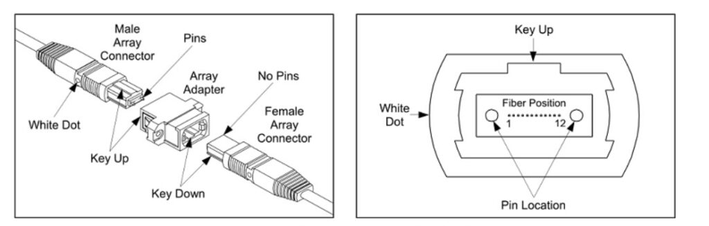
Fig. 10 Schematic of Type A MPO Array Adapter
Type B adapters MATE fiber position 1 to fiber position 12 from one cable end to a new cable end and are KEY-UP to KEY-UP.
For the convenience of our customers, Precision OT provides a “Cable Builder” for basic Fiber Jumpers and MPO/MTP® Cables. Successful installation of a fiber-optic network employing MPO cables, connectors and adapters relies on several considerations. For specific application questions and/or special MPO cable requests, contact the optical network experts at Precision OT.