
In the first two blogs of our “Into the Transceiver-verse” series, we talked about how to choose the right transceivers for your application and summarized the transceiver types available. In this blog, we’ll focus on 3 techniques to help overcome data rate and distance challenges. Throughout the history and the evolution of transceivers, demand has driven the push for sending more data, faster and for longer distances. As data rates increase, effects such as attenuation and chromatic dispersion become a limiting factor with respect to link length.
3 techniques which can be used to push data rates to the next level include:
- Adding Optical Lanes
- Forward Error Correction
- Pulse Amplitude Modulation 4
Adding Optical Lanes
One of the simplest ways to help data go faster is to add optical lanes. Starting with the early form factors like GBIC and SFP back in the late 90’s, transceivers could carry 1 to 2.5Gbps data rates over a single optical lane. In the early 2000’s, the standards for 10G were developed and from that came several form factors but ultimately the SFP+ became the most popular due to having the lowest power draw and a slim profile enabling higher port density. 10G was the first time we saw the implementation of multiple optical signals within a pluggable transceiver – this type of design would later become much more prominent in higher data rates. By 2007, manufacturers were able to develop cost effective solutions for a 40G
QSFP+ solution. The QSFP+ is essentially 4 SFP+s put into one unit. This hardware utilizes 4 optical signals carrying 10G but there are two types of optical connector interfaces that were birthed from there.
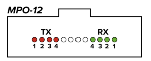
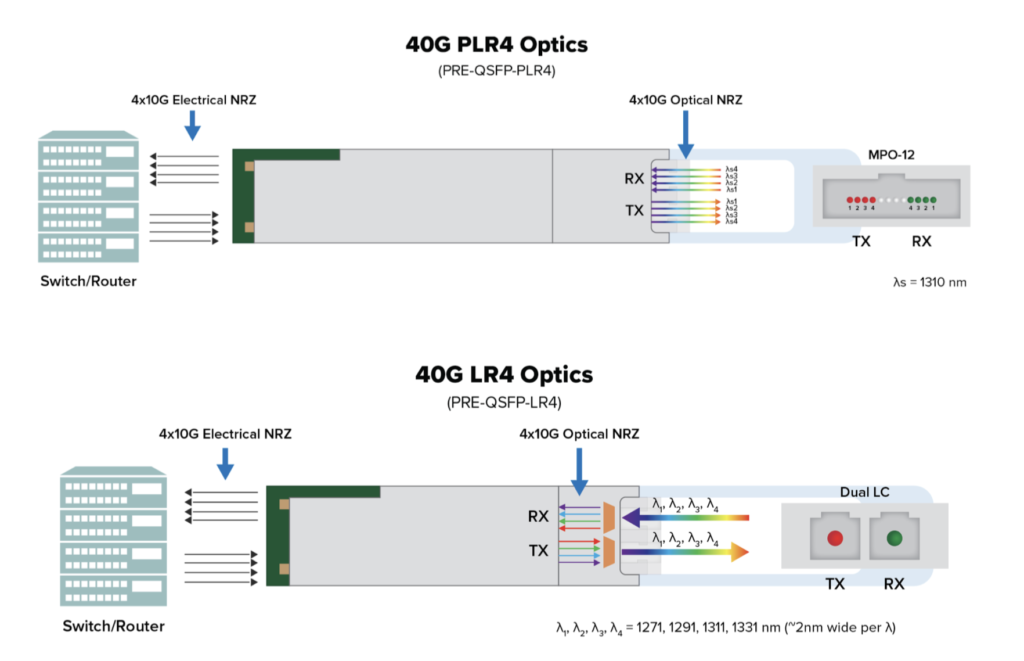
One method to accomplish 40G is by transmitting 4 dedicated lanes of the same wavelength along parallel fibers. Each lane on the MPO TX output carries a separate 10G data rate. This design, shown in Figure 2a, is useful for break out connections – with the QSFP using an MPO-12 you can connect it to 4 SFP+’s on the far end of the connection.
Alternatively, instead of 4 separate dedicated lanes, the 4x 10G optical signals can all be muxed/demuxed internally in the transceiver via a duplex LC connector as shown in Figure 2b. This design development helped network operators save boat loads of money in being able to re-use the same LC duplex fiber that they were using for their SFP+ as they migrated to the QSFP+.
By continuing to increase the number of lanes, 40G was quickly followed by 100G. Figure 3 shows the first 100G implementation: 10 lanes of 10G.
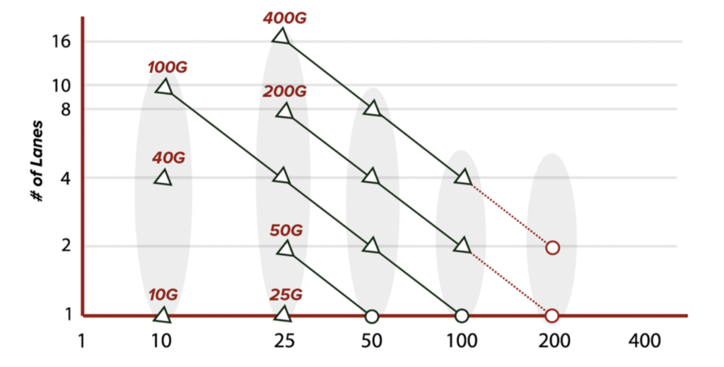
Shortly thereafter TOSAs and ROSAs capable of 25G were developed. By combining 4 of them into the same form factor, 100G (4x25G) was possible and development continued on in a similar fashion. However, adding optical lanes can only get us so far. To push higher data rates on longer links, additional techniques are needed.
Forward Error Correction (FEC)
In a perfect world, the data we transmit through various communication channels would always arrive complete and unaltered – exactly as we send it. Realistically speaking, this is not the case. A variety of factors can distort the signal or even completely prevent data from reaching its intended destination. This is where Forward Error Correction (FEC) comes into play.
With FEC, a portion of the bandwidth is dedicated to error correcting code meant to assist the receiver with interpreting noisy or unreliable data. In practice, FEC works by lowering the required Optical Signal to Noise Ratio (OSNR), which can help an otherwise unusable signal function normally. By encoding the original data/message prior to transmission with redundant data, network operators can reduce OSNR requirements and increase wavelength travel distance significantly. FEC adds extra/redundant information to the transmission, so the receiver can computationally “recover” from any errors. For example, you can take a 10G signal (which is actually transmitting 10.325Gbps with overhead) and you pad it up to 11Gbps (7% overhead) and now you’ve taken what can normally go 80km and allowed it to go 120km or beyond because you are able to recover from a weaker signal (ie., one with more dispersion and reduced OSNR).
Note that FEC is typically performed and supported by the host device. However, in some cases such as certain Pulse Amplitude Modulation 4 (PAM4) technologies, FEC is implemented on the transceiver itself. When not in the transceiver it is up to whichever host switch or router you are using to have this FEC enabled. Luckily, FEC has become widely used and has evolved over the years to become part of nearly every standard. There are several different types of FEC, all of which send error correcting code:
- 1st Gen – RS-FEC – 6% overhead for ~6dB of net coding gain. (RS = Reed Solomon)
- 2nd Gen – EFEC – 7% overhead for ~8-9dB of net coding gain. (E = Enhanced)
- 3rd Gen – SD-FEC – 20-25% overhead for 10-11dB coding gain. (SD = SoftDecision)
Another important point regarding FEC is that it must be “bookended”. In other words, FEC must be exactly the same on each side of the link or it will be inoperable. See FEC in 100G networks and beyond to learn more about types of error correcting codes and how they are effectively employed to reduce bit-error rate(BER) and increase network reliability.
Pulse Amplitude Modulation 4 (PAM4)
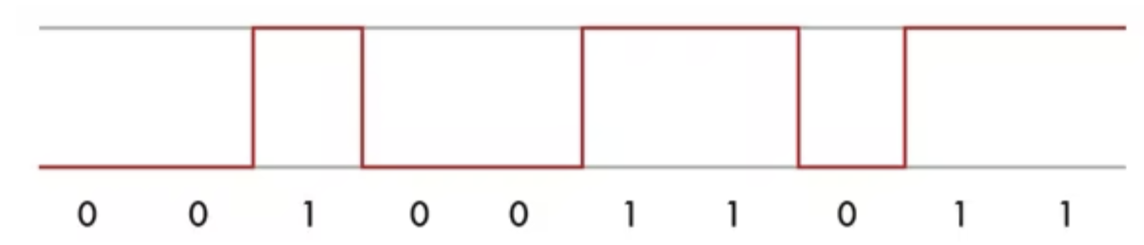
Modulation, in communication, is a technique for impressing information (voice, music, picture, or data) on a radio-frequency carrier wave by varying one or more characteristics of the wave in accordance with the intelligence signal. The simplest form of modulation is Intensity Modulation with Direct Detection (IM-DD) and the most common version of IM-DD is Non-Return to Zero (NRZ). It essentially means “bright for a 1, dim for a 0”. Historically, fiber optic systems were all purely NRZ based. NRZ is your typical binary code and most if not all 10G and below optical technology is based on NRZ. Another way to describe NRZ, shown in Figure 4, is PAM2 (Pulse Amplitude Modulation 2).
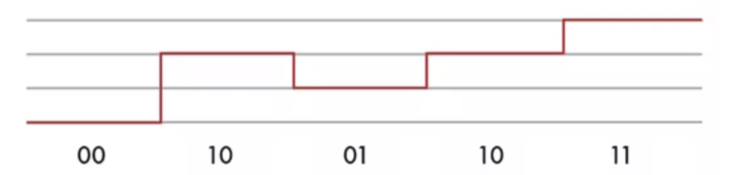
PAM4 is a modulation scheme that combines two bits into a single symbol with four amplitude levels. This effectively doubles a network’s data rate. The 4 indicates the number of “levels” as shown in Figure 5 below.
In recent years we have seen PAM4 become more and more common. So how is it different from what we see in lower data rate hardware such as 1G and 10G? PAM4 allows us to overcome limitations in channel technology. We can double the throughput in roughly half the bandwidth. PAM4 allows the continued use of existing channel technologies while increasing throughput.
But if PAM4 is so great, why have we not been transmitting 2 bits of data per 1 optical pulse all along? Put simply, the TOSAs (Transmitter Optical Sub Assembly) and ROSAs (Receiver Optical Sub Assembly) that can process PAM4 are much more complex than the typical NRZ / Manchester Phase Encoding (MPE) / 8B/10B encoding OSAs. And while PAM4 does double the number of bits in serial data transmissions by increasing the number of levels of pulse-amplitude modulation, it also creates a penalty on signal to noise ratio (SNR). For this reason, PAM4 is more ideally suited for short-haul high bandwidth applications, such as 400G up to 40km distances. PAM4 and even higher modulation are going to be the key for driving higher data rates in the future.
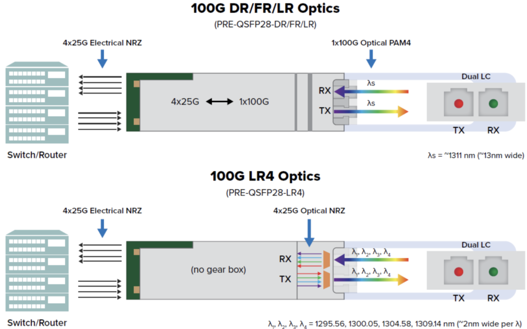
One notable implementation of PAM4 is in 100G transceivers. The QSFP28-DR/FR/LR transceivers are single lambda 100G PAM4 transceivers, which means there is one wavelength capable of transmitting up to 112Gb/s. The difference between DR, FR, and LR is the max distance that each transceiver can achieve. DR is for links up to 500 m, FR up to 2 km, and LR up to 10km. The main difference in these newer 100G transceivers is the internal gear box in the PRE-QSFP28-DR/FR/LR that converts from 4x25G NRZ electrical lanes to 1x100G PAM4 optical lane. These new transceivers also implement FEC inside the Digital Signal Processor (DSP) of the transceiver (host independent). Figure 6a shows a schematic of the single lambda QSFP28-DR/FR/LR transceiver compared to Fig. 6b, the 100G LR4 optic (4x25G Optical NRZ). For additional information check out the 100G Lambda MSA which defines 100G PAM-4 optical signaling and encoding.
Our above review of chromatic dispersion and the introduction to 3 techniques for overcoming data rate and distance challenges provides us with a better understanding of hardware/software changes necessary to achieve 40G – 400G networking and beyond. Adding optical lanes helps us push data further while reducing the impact of chromatic dispersion. FEC helps receivers interpret unreliable or noisy data, effectively increasing the distance we can push higher data rates. And PAM4 helps us essentially double the data of a single optical signal. These three features implemented into the same transceiver enable the leap from 10G up to 400G and higher (800G is in development with 1.6Tbps on the roadmap).
Thanks for taking this journey “Into the Transceiver-verse” with us. Transceiver tools and technology are poised to continue pushing the limits of current optical networking capabilities. For all your current and future networking needs, contact Precision OT’s team of experts.